18
NOVEMBER-DECEMBER2014
d
&
ri
DEMOLITION AWARDS
Thedemolition specificationonly
permitted theuseof one entranceonto site. In
normal circumstances a site entrancewould
usuallybe formedwhere the façades arenot
being retained.However, in this case thenon-
retained façadewasdirectlyoppositeTCEs
offices, so theonlyotherpositionavailablewas
along theNBS façade throughan existing shop
front.
ALLOWINGACCESS
Following swept pathanalysis of the types of
constructionvehicles required to service the
project, the shop front at 4NBSwas selected
as theonlypossibleusable entrance. To ensure
this locationwouldwork, furtherdetailed site
investigationswereundertaken to establish
the constructionof thebasement andground
level structure.Keltbray’s temporaryworks
engineersprovideda scheme that involved the
installationof over 300acrowprops to support
the existingground floors, installing150m
2
(1,615 ft
2
) of steel plates toprotect the existing
ground floor, installationof a temporary
bridge structure spanning the existing light
well between thepavement and shop front and
finally the excavationand constructionof a
concrete slab (crossover) toprotect the existing
serviceswithin thepavement.
With the abovekeyworks complete, the
site teamwere able to takedeliveryof theplant
toundertake the first element of demolition
to the rear low level courtyard structures.
However,witha restrictedheight clearanceof
3.7m (12.2 ft), the type and sizeof plantwas
limited.
Inaddition to the site constraints,NBSwas
reduced toa single carriagewaydue toanother
construction sitebeingdirectlyopposite
usingapit lane to service that site. From the
offset agreementswereput inplace to ensure
the sectionof thepit lanedirectlyopposite
theKeltbray site entrancewas kept free at all
times allowingaccess/egress toW5.However,
to ensure these agreementsweremaintained,
weeklyanddaily coordinationmeetingswere
heldbetween the site construction teams.
Once the low level demolitionwas complete
the site team could focus on thenext key
resources for the successful deliveryof the
project, thedemolition tower crane and the
foundations for the façade retention system.
The tower cranewasdesigned tobe free
standing,with coverageover thewhole site. In
planning the tower crane erection,Keltbray
andHTCwere restricted toonlyusingNBS
for thepositionof the erectingmobile crane.
Thepositionof thiswithinNBS alsohad
to contendwith the external scaffoldand
hoardingof theW4project, so the erecting
mobile crane selectedwas a250 tonnewith fly
jib to reachover the existingbuildings. The
foundations for the façade retentionwere all
designedas reinforced concrete,with20300
θpiles at 22mdeep.With the tower crane
erectedand sufficient foundations cast the
erectionof the façade retention commenced,
threemonths from taking initial possessionof
the site.
Deliveries of the façade retention steelwork
had tobe carriedout between5and6am. The
initial phaseof the façade retentionhad tobe
undertakendurationnight shifts, reducing
the interfacewith thegeneral public as the
first sections of the steelworkpenetrated the
pavement zone. Thesewere also restricted to
sixhourspernight andonly fournights of the
week.
Once the steel framehadpassed the
pavement zonewithprotectionafforded to
thepublic, the façade retention installation
continuedduringnormal day shifts, however
stillwith theoccasional night timeworking
where interfacewith thepublic existed (the
façade retention systemweighted inat 130
tonnes).
Toprogress thePortland stone façade and
stonedormerdismantlingworks above the
5th floor cornice as earlyaspossible in the
programme,Keltbraydesignedand installeda
cantilever scaffoldat 4th floor to support the
access scaffold required togainaccess to the
façades beingdismantled.
GROUNDWORKS
Another reasonwhyKeltbraywon the tender
was their ability toadvancemuchof the future
groundworksduring thedemolitionphaseof
theproject. Thegroundworks involved the
removal of the existingbasement structure
and foundations at the locationof themini
piles. Installationof 40450θpiles at 22mdeep
completewithvertical steel beams (known
as kingposts), a3m (9.8 ft) reduced level
excavationwith constructionof concretewall
panels between thekingposts and40m (131.2
ft) of 3mdeepunderpins.
Tomaintain thehighprofileof theproject,
TCE instructed thedesignand installation
of awrap to cover theoutsideof the façade
retention steel frame along theRegent Street
andNBS elevations, andanadditional
secondary steel framewasdesignedand
erected to the existingmain support steel to
ensure thewrapwas in straight line and level.
Due to thehigh cost of thewrap, façade
movementmonitoring couldnot be carried
out externally since thiswouldhave required
holes tobe cut in thewrap toview the targets.
Thebasement linemonitoringwasdone
prior to the installationof thewrapbut the
remainingmonitoring couldonlybe carried
out from inside theproject of theworking
floors inandaround thedemolitionworks.
Rotating targetswere installed to the reveals of
the existingwindows toallowview externally
for thebasement line and then internally
during theworks.
Once the façade retention steel framewas
installedand signedoff and thePortland stone
and thehigh level roof demolitionworkswere
completed themain structural demolition
commenced from the5th floor level down to
the existingbasement level.
■
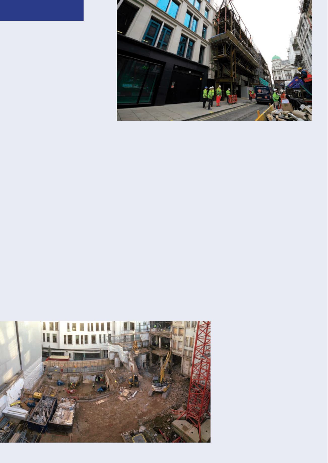
Site entrance situated in the retained
façade onNewBurlington Street and
neighbouringW4 Construction site
pit lane onNewBurlington Street
Structural demolition being carried out andwaste
segregation in progress


