THE KNOWLEDGE
INTERNATIONAL AND SPECIALIZED TRANSPORT
■
NOVEMBER 2013
38
was turned upside down (now the ram
protrudes from the bottom), a load
bearing platform was constructed around
the bottom of the jack and the climbing
jack was born.
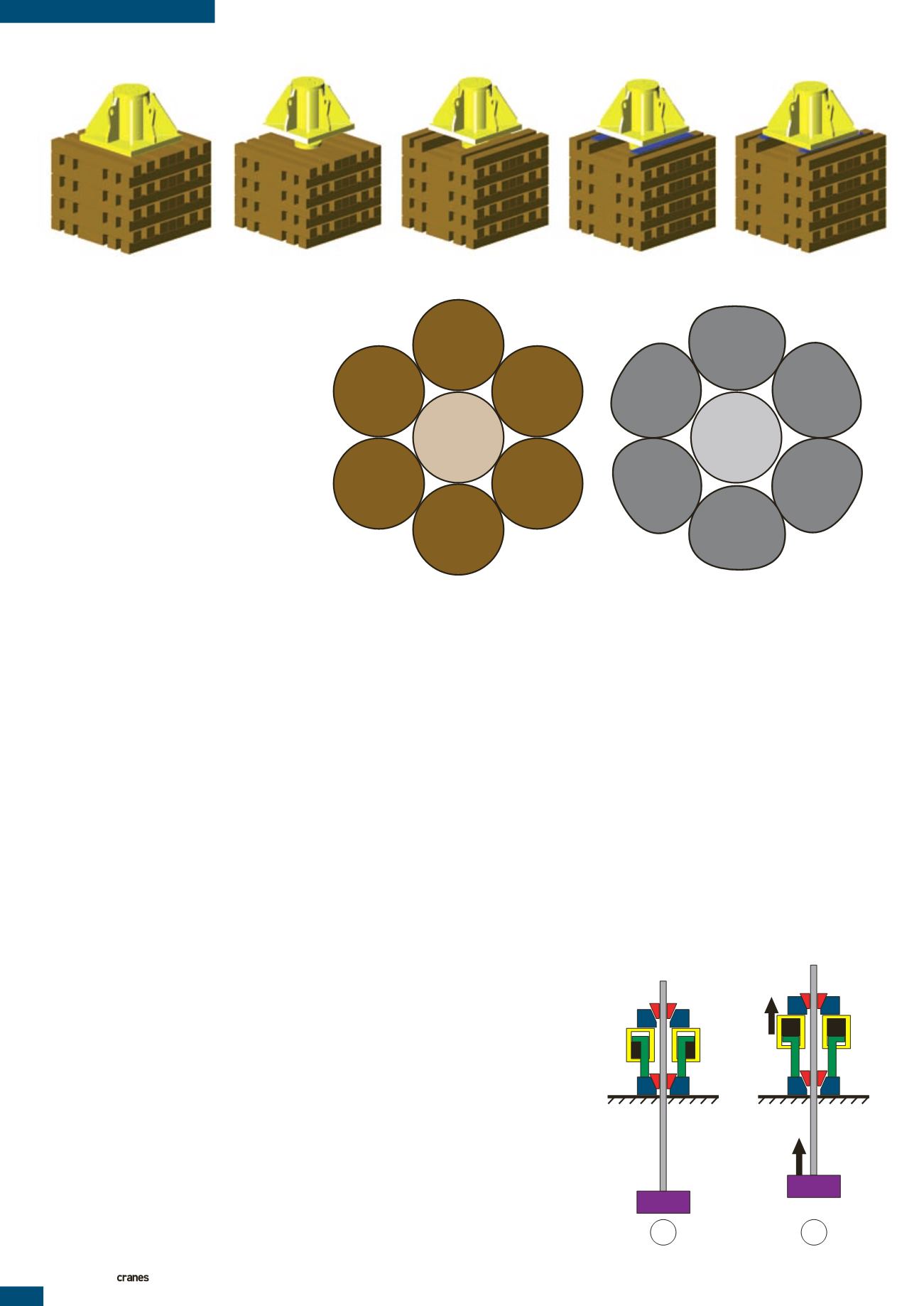
There are seven basic steps in the cycle
of a climbing jack, see Figure 1.
Step 1: jack is set up
Step 2: ram is extended
Step 3: hardwood timbers are placed parallel
underneath the jack (criss-cross)
Step 4: steel strips are placed onto
the hardwood
Step 5: the jack is lowered on the steel strips
and the ram is retracted
Step 6: the void underneath the jack is now
filled up with hardwood
Step 7: the ram is extended continue
from step 2
NOTE:
The steel strips that are used are there
to create sufficient space between the jack
and the previous layer of timbers, so that
the timbers of step 6 can be easily inserted
underneath the jack.
The hardwood that is used as jacking
timber is mostly called ekki or azobe. They
are both of the same Ochnaceae botanic
family. It is found in West Africa (among
others in Cameroon, Ivory Coast, Nigeria
and Sierra Leone). Once the wood is dried
and the moisture content has fallen below
12 % this wood is extremely durable and
hard. Besides jacking timber, this wood
is also used for rail road crossties and
harbour work. Machining with hand tools
(drill or saw) is almost impossible, the
final dimensions are commonly achieved
on a lathe.
According to the Center of Wood
Anatomy Research, azobe has a
maximum compression, or crushing,
strength of 914 to 1,050 kg/cm
2
)
(13,000 to 15,000 PSI). This makes it very
suitable for jacking operations. One thing
to keep in mind, though, is its specific
gravity of 1,120 kg/m
3
(70 lbs/ft
3
), it is
heavier than water and it will sink.
Strand jacks
While on the subject of jacks, it is a small
jump to strand jacks. Strand jacks have
been around for quite a while but not in a
heavy lift application. They were originally
used for post-tensioning of concrete
beams when used for large spans such
as bridges. Nowadays, strand jacks are
found in horizontal applications as pulling
tools, for example, for large load outs, or
in vertical applications as lifting tools on
cranes, lifting towers or gantries. They can
even be used upside down.
A strand jack is a hollow jack that is
fed with die-formed 18 mm strands of
15 tonne capacity wire rope. The strands
are held in place by wedges. There is a
set in the top of the jack and a set in the
bottom. The strands are die-formed (see
Figure 2) to allow the wedges to have a
tight grip on the strand. Higher capacity
strand jacks use more strands, the strand
pattern is always symmetrical to avoid
eccentric loads on the jack.
To lift a load, the strand jack follows a
sequence of activities, see Figure 3.
Step 1: the load is suspended by the lower
wedges, the upper wedges are open
Step 2: the upper wedges close and the ram
extends. The load is now suspended by
the upper wedges and is raised. This
motion allows the lower wedges to
open and stay open
Step 3: at the end of the stroke the lower
wedges close again and the downward
motion (ram retract) transfers the
load to the lower wedges, this motion
allows the upper wedges to open
and stay open
Step 4: once fully retracted, the upper wedges
close and the ram extends, the load is
now suspended by the upper wedges
and is raised, this motion allows the
lower wedges to open and stay open.
The above sequence repeats itself until
the load has reached its required height.
An advantage of strand jacks is that
one can achieve a high lifting capacity
(750 tonnes or more per strand jack is not
FIGURE 1
Using hydraulic jacks to raise a load to a significant height is a laborious process
Standard strand
Die-shaped strand
FIGURE 2
Standard strand on the left and a die-formed strand for strand jacking
FIGURE 3
Operating sequence for strand jacks
LOAD
START
OPEN
CLOSED
1
LOAD
RAISE
CLOSED
OPEN
2


